Home › Unlabelled ›
Phasor Diagram In Ac Circuit : (PDF) Analysis and design of three-phase rectifier ... / In case of series rl circuit, resistor and inductor are connected in series, so current flowing in both the elements are same i.e ir = il = i.
Phasor Diagram In Ac Circuit : (PDF) Analysis and design of three-phase rectifier ... / In case of series rl circuit, resistor and inductor are connected in series, so current flowing in both the elements are same i.e ir = il = i.. Rl circuit for drawing the phasor diagram of series rl circuit; In this video, phasor, and phasor diagram for ac circuits have been explained. Alternating current (ac) is a type of electric current that reverses its direction periodically in contrast to the direct current (dc) which flows in a single direction. (i) if xl > xc, (xl−xc) is positive and phase angle ϕ is also positive. I consider that the angle of the voltage and current phasors in the shown diagram are given.
Phasor diagram for an rlc series circuit. If you need to add or subtract phasors. I think actually the exact definition may differ depending on the field you are worrying. Figure 15.12 the phasor diagram for the rlc series circuit of figure 15.11. But first, why study ac circuits?
Learn AC Circuits Online | Phasor Diagram | Ekeeda.com ... from i.pinimg.com A phasor is a complex number in polar form that you can apply to circuit analysis. When you plot the amplitude and phase shift of a sinusoid in a complex plane here is a diagram of a voltage phasor as a rotating vector at some frequency, with its tail at the origin. The phasor diagram is drawn corresponding to time zero ( t = 0 ) on the horizontal axis. The circuit containing only a pure resistance of r ohms in the ac circuit is known as pure resistive ac circuit. Here a link for you to check out, call it a math refresher phasor diagram and phasor algebra used in ac circuits. It is sometimes helpful to treat the phase as if it defined a vector in a plane. In this section, we study simple models of ac voltage. Ac circuits and ac electricity, explained using animated graphs and phasor diagrams.
A phasor is a complex number in polar form that you can apply to circuit analysis.
When you plot the amplitude and phase shift of a sinusoid in a complex plane here is a diagram of a voltage phasor as a rotating vector at some frequency, with its tail at the origin. This demonstration shows a phasor diagram in an ac series rlc circuit. Graph of a phasor as a rotating vector. Returning now to the discussion of the reluctance motor phasor diagram in fig. Due to the phase difference phasor diagram for an rlc series circuit: From phasor diagram, the phase angle between υ and i is found out from the following relation. The voltage across a capacitor lags the current. Capacitive reactance and phasor diagrams. Note that the phase angle, the difference in phase between the voltage and the current in an ac circuit, is the phase angle associated with the impedance z of the circuit. A short cut that can be used to determine the amplitude and phase of current in an ac circuit is the phasor diagram. Interpret phasor diagrams and apply them to ac circuits with resistors, capacitors, and inductors. Define the reactance for a resistor, capacitor, and inductor to help understand how current in the circuit behaves compared to each of these devices. Phasor diagrams are diagram representing alternating current and voltage of same frequency as vectors or phasors with the phase angle between them.
You probably live in a house or appartment with sockets that deliver ac. Rl circuit for drawing the phasor diagram of series rl circuit; We can also represent the purely capacitive circuit lags the current by 90° by a phasor diagram. Figure 15.12 the phasor diagram for the rlc series circuit of figure 15.11. The phasor diagram is drawn corresponding to time zero ( t = 0 ) on the horizontal axis.
Inductor : Inductive Reactance from www.dnatechindia.com This is an ac circuit containing a voltage source v(t), a capacitor of capacitance c and a switch connected to it. Define the reactance for a resistor, capacitor simple ac circuits an ac generator produces an emf of amplitude 10 v at a frequency determine the voltages across and the currents through the circuit. In ac electrical circuits, this is the. I consider that the angle of the voltage and current phasors in the shown diagram are given. Phasors are used for a lot more than just ac circuit analysis. 9.17a that draw power phasor diagrams for the circuit in problem 1. Your radio, television and portable phone receive it, using (among others) circuits like those below. This demonstration shows a phasor diagram in an ac series rlc circuit.
This is an ac circuit containing a voltage source v(t), a capacitor of capacitance c and a switch connected to it.
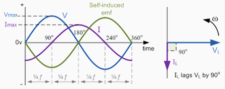
Calculate the value and sign of the phase. A phasor is a complex number in polar form that you can apply to circuit analysis. The circuit consists of a resistor with resistance. Because the components of the circuit are. Rl circuit for drawing the phasor diagram of series rl circuit; 9.17a that draw power phasor diagrams for the circuit in problem 1. Draw the voltage and phasors with their tails at the origin of the coordinate system. Define the reactance for a resistor, capacitor simple ac circuits an ac generator produces an emf of amplitude 10 v at a frequency determine the voltages across and the currents through the circuit. In certain circuits when current reaches its maximum value after emf becomes maximum then current is said to lag behind emf. Capacitive reactance and phasor diagrams. (i) if xl > xc, (xl−xc) is positive and phase angle ϕ is also positive. In the following figures the phasor diagrams are not illustrated by the. Phasor diagrams are a way of representing sinusoidal waveforms such that you can add and subtract them and get correct answers.
So, take current phasor as reference and draw it on horizontal axis. In case of series rl circuit, resistor and inductor are connected in series, so current flowing in both the elements are same i.e ir = il = i. Interpret phasor diagrams and apply them to ac circuits with resistors, capacitors, and inductors. Graph of a phasor as a rotating vector. When you plot the amplitude and phase shift of a sinusoid in a complex plane here is a diagram of a voltage phasor as a rotating vector at some frequency, with its tail at the origin.
Phase Relationships in AC Circuits from hyperphysics.phy-astr.gsu.edu Ac circuits and ac electricity, explained using animated graphs and phasor diagrams. (i) if xl > xc, (xl−xc) is positive and phase angle ϕ is also positive. The circuit containing only a pure resistance of r ohms in the ac circuit is known as pure resistive ac circuit. \phi is the phase angle, equal to the phase difference. You probably live in a house or appartment with sockets that deliver ac. In ac electrical circuits, this is the. A phasor is a complex number in polar form that you can apply to circuit analysis. And at the end, voltage and current relationship between the basic circuit.
But first, why study ac circuits?
Ac circuits and ac electricity, explained using animated graphs and phasor diagrams. Define the reactance for a resistor, capacitor, and inductor to help understand how current in the circuit behaves compared to each of these devices. Here a link for you to check out, call it a math refresher phasor diagram and phasor algebra used in ac circuits. The diagram describes a circuit that contains two elements connected in parallel to an ac source. I consider that the angle of the voltage and current phasors in the shown diagram are given. Interpret phasor diagrams and apply them to ac circuits with resistors, capacitors, and inductors. Phasor diagram for an rlc series circuit. The voltage across a capacitor lags the current. In ac electrical circuits, this is the. Note that the phase angle, the difference in phase between the voltage and the current in an ac circuit, is the phase angle associated with the impedance z of the circuit. Capacitors store energy on their conductive plates in the form of electrical charges. Returning now to the discussion of the reluctance motor phasor diagram in fig. In case of series rl circuit, resistor and inductor are connected in series, so current flowing in both the elements are same i.e ir = il = i.